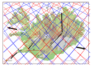
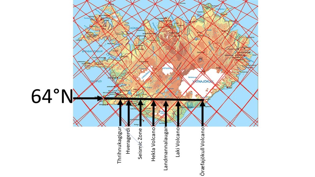
Geodetic measurements show that plate separation across Iceland is directed approximately N15°E (equivalent to ~105° azimuth). This regional extension is commonly illustrated on geological maps by symmetrical vectors on either side of the island.
Yet the structural grain of the East Volcanic Zone at ~64°N trends N42°E, implying a misalignment of about 27° relative to the plate motion vector.
In classical fracture mechanics, extension should generate rifts perpendicular to the direction of maximum tensile stress. The observed geometry in Iceland therefore indicates that additional controls modify the stress field within the crust.
One plausible mechanism is the influence of organized **mantle convection patterns. If the upper mantle is structured into long, coherent convection rolls, their boundaries may impose a polygonal framework on the lithosphere. These boundaries can act as zones of mechanical weakness, guiding the localization and اتجاه of rifting.
In this framework, the regional plate-separation vector (N15°E) is not directly expressed at the surface. Instead, extension is effectively reprojected along the geometry of convection-driven domains, producing rift segments such as the East Volcanic Zone with an orientation of N42°E.
A map published by Iceland GeoSurvey, showing inferred convection-roll division lines, highlights this systematic angular discrepancy.
Map showing basic alignment of volcanic and seismic zones, along with the two vectors of plate separation.
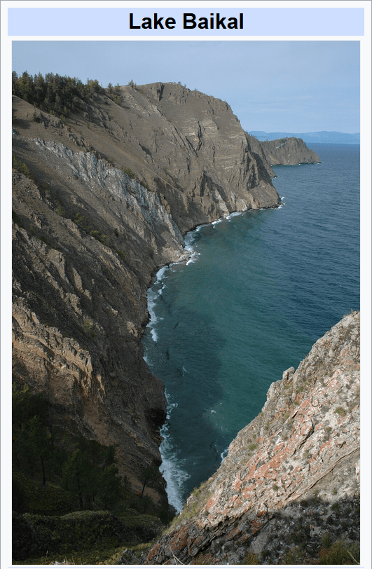
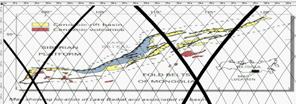
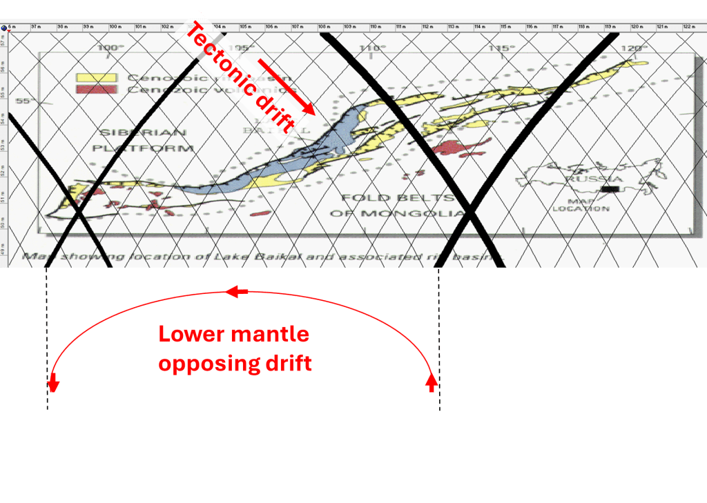
Examining Lake Baikal suggests that it can be interpreted as a surface expression of a deep-seated geodynamic process, potentially associated with a lower mantle convection roll extending 15° from east to west.
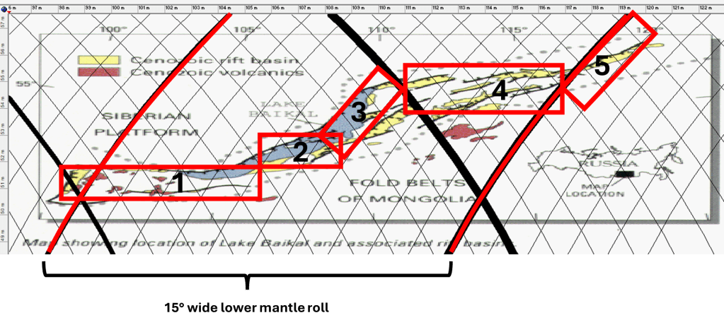
The Baikal Rift Zone can then be subdivided into five distinct structural sections, as shown below:
Western Segment – A deep, east–west–oriented basin forming the western extremity of both the lake and the rift system.
Central Basin – The deepest portion of the lake, representing the core of rifting activity and maximum crustal thinning.
Northeastern Segment – A structurally complex area aligned with the boundary between adjacent tectonic or mantle-flow domains (interpreted here as polygonal convection cells).
En Echelon Rift Systems – A series of east–west–trending, staggered rift structures situated between boundaries of different lower mantle flow layers, suggesting segmented deformation linked to deeper dynamics.
Eastern Termination – The distal end of the rift complex, where deformation becomes more distributed and transitions into surrounding tectonic regimes.
The principal rift axis appears to be located at the intersection of the central basin (2) and the northeastern segment (3), where structural and dynamic influences converge.
Lake Baikal is the deepest lake on Earth, reaching a depth of about 1,642 meters, and contains approximately 20% of the world’s unfrozen freshwater, making it one of the most significant hydrological reservoirs on the planet.
In this interpretation, the convection roll rotates counter to the direction of tectonic plate drift, helping to sustain and localize an extensive continental rift system. To show how the tectonic drift is opposed by the convection roll of lower mantle, this drawing below is added. It is not to scale, and the upper mantle convection rolls are omitted for clarity. But this is how it works.
The Baikal Rift Zone is often explained in conventional geology as a result of:
Far-field stresses from the collision of the Indian Plate with Eurasia
Lithospheric extension within the Eurasian Plate
Here, a deeper mechanism is added:
A large-scale lower mantle convection roll imposes stress on the tectonic plate.
Rotating opposite to plate motion, it thereby enhances extensional stress, stabilizing and sustaining the rift over long geological timescales.
The en echelon faulting often reflects oblique extension, which can result from interacting flow directions between mantle layers.
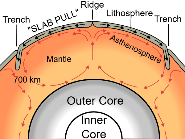
All of this begins with a drawing found all over, a simple section of mantle rolls. Basically, those are two circles turning in opposite direction against each other:
This is simple, accepted as a guess, though. Analysing this is a bit more complicated than one might think at first. Here is an example of how to handle that:
I — FOUNDATIONS
Chapter 1 — The Making of a Model
1.1 Plate tectonics as a descriptive model
1.2 Mantle plumes vs global structure
1.3 Missing geometry in geoscience
1.4 The need for a unifying framework
1.5 Observational inconsistencies
Chapter 2 — First Observations of Order
2.1 Iceland as a key to global structure
2.2 Regular spacing of volcanic zones
2.3 The 30° and 90° patterns
2.4 Symmetry across hemispheres
2.5 The Ring of Fire as a system
Chapter 3 — From Observation to Hypothesis
3.1 Recognizing repeating units
3.2 The idea of convection rolls
3.3 Linking surface features to deep structure
3.4 Early geometric interpretations
3.5 Formulating a testable model
II — THE CONVECTION ROLLS MODEL
Chapter 4 — The Mathematical Framework
4.1 The global equation of mantle rolls
4.2 The 1.5° discretization
4.3 The role of latitude (32°)
4.4 Directional equations
4.5 Spherical corrections
Chapter 5 — Vertical Structure of the Earth
5.1 Earth’s layered structure
5.2 120 km, 410 km, 670 km discontinuities
5.3 Equal height–width condition
5.4 Rayleigh-Bénard convection in Earth
5.5 Stability of convection rolls
Chapter 6 — Global Distribution of Mid-Ocean Ridges
6.1 Ridge alignment and geometry
6.2 Atlantic vs Indian vs Pacific
6.3 90° relationships
6.4 Iceland as a ridge–roll interface
6.5 Implications for seafloor spreading
Chapter 7 — Subduction Zones and the Ring of Fire
7.1 Convergent boundaries as part of the same system
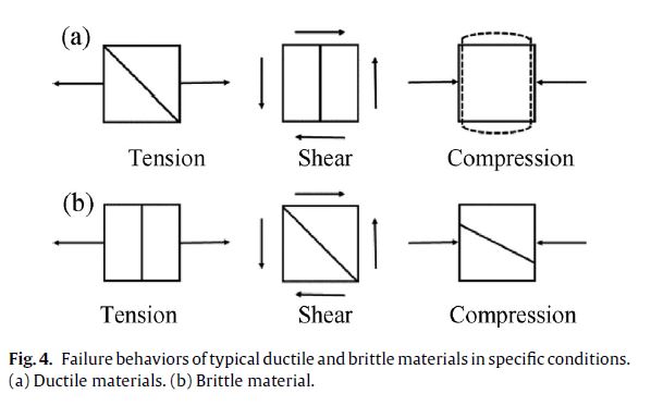
A tectonic plate is brittle at the top, but most of it is ductile. The fractures of ductile and brittle materials are different, and therefore magma can find different flowlines within different depth levels of the plate. This is explained in the article: https://www.sciencedirect.com/science/article/abs/pii/S009364131730561X as shown below:
Failure of brittle and ductile material theory (from Jiefei Gu, Puhui Chen – A failure criterion for isotropic materials based on Mohr’s failure plane theory).
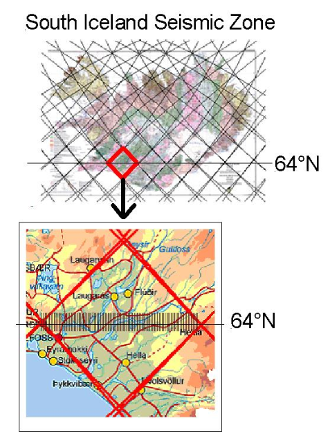
The polygons that characterize the southern half of Iceland are remarkably regular, allowing simple geometric patterns to emerge clearly. In both brittle and ductile layers, deformation occurs systematically: brittle layers are affected primarily by tension, while ductile layers accommodate shear. As a result, faulting tends to propagate from one corner of each polygon to the opposite corner. Within the volcanic zones, tension fractures are particularly evident, as illustrated in Figure (b).
Figure a: Features of the four polygons in South Iceland along 64th parallel.
The southern region of Iceland exhibits a high degree of polygonal regularity, enabling clear geometric relationships to be identified. Both brittle and ductile layers are systematically deformed: brittle deformation is dominated by tension, while ductile deformation accommodates shear. In both cases, faulting and strain localization occur preferentially along diagonals connecting opposing polygon corners.
This structural organization is particularly evident along the 64th parallel, where the polygons approach a near-ideal diamond geometry. Within these polygons, east–west-oriented lineaments subdivide the structure along corner-to-corner axes. These features are independently supported by geophysical observations within the South Iceland Seismic Zone, where detailed measurements confirm the presence of such structural divisions.
Furthermore, the regional stress field associated with this polygonal framework predicts the development of volcanic fissures oriented NE–SW. This prediction is consistent with observed fissure swarms in Icelandic volcanic zones, indicating that their orientation is controlled by the underlying geometric and mechanical structure.
A notable deviation occurs on the Reykjanes Peninsula, where the central polygonal axis bends southward in its western segment. This deflection corresponds to its interaction with the Reykjanes Ridge and the adjacent polygonal system to the southwest, reflecting boundary-induced modification of the otherwise regular structure.
In contrast, other regions of Iceland display a more uniform configuration, with well-defined east–west axes extending directly between polygon corners, consistent with the predictions of the model.
Figure b: The SISZ with the earthquake faults marked as parllel N-S oriented lines.
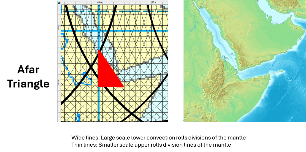
The Afar Triangle connects with the key equatorial division point, as the rift valley extends to there:
The Afar Triangle occupies a key geometric position within the mantle flow system. It is located at what can be interpreted as a corner of a larger convection framework, where different structural directions converge.
Its triangular shape is not incidental. The geometry is well defined:
the southern boundary trends roughly east–west
the western boundary trends north–south
the eastern boundary trends northwest–southeast
This configuration is consistent with earlier observations that similar directional patterns frequently appear in regions influenced by mantle convection rolls. In particular, these orientations correspond to the dominant structural directions expected where mantle flow organizes into a grid- or diamond-like pattern that is reflected at the surface.
The Afar Triangle therefore represents more than a tectonic junction. It marks a point where:
different directions of mantle flow interact
deformation becomes concentrated
and surface structures take on a geometrically organized form
This makes it a critical location within the broader East African Rift system.
A Key Junction in the African Rift System
The importance of the Afar region becomes especially clear when viewed in relation to the East African Rift.
The rift system in eastern Africa trends predominantly NE–SW, forming a broad zone of distributed extension across the continent. As this system propagates northward, it meets the Red Sea rift at Afar.
This intersection is not random.
Instead, it reflects the meeting of:
a continental-scale extension zone (East African Rift)
and an oceanic spreading system (Red Sea and Gulf of Aden)
At this junction:
the geometry of the rift system changes
deformation becomes more focused
and the transition from continental rifting to oceanic spreading is clearly expressed
Connection to Mantle Roll Geometry
From the perspective of mantle dynamics, the Afar Triangle can be interpreted as a surface expression of deeper mantle currents.
If mantle convection is organized into rolls and their intersections form angular or diamond-shaped patterns, then:
the edges of the Afar Triangle align with these structural directions
the triple junction reflects a node within this system
This provides a coherent explanation for:
the triangular geometry
the alignment of rift branches
and the concentration of tectonic activity in the region
Why Afar Matters
The Afar Triangle is therefore a key point in the Great Rift of Africa:
It is where a NE–SW-trending continental rift system meets a north–south-oriented oceanic spreading system, within a geometric framework that reflects deeper mantle flow structures.
This makes it one of the clearest locations on Earth where:
surface tectonics
geometric patterns
and mantle dynamics
can be studied together as parts of a single system.